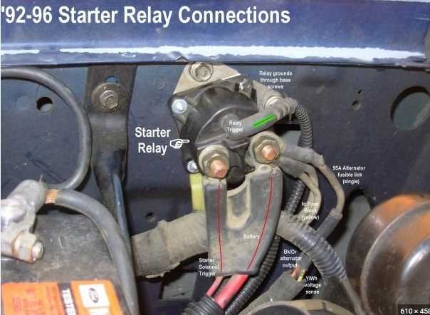
When it comes to starting your vehicle, the starter relay plays a crucial role in the process. This small electrical component is responsible for sending power from the battery to the starter motor, allowing your engine to turn over and start running. Understanding the wiring diagram for the starter relay is essential for proper installation and troubleshooting.
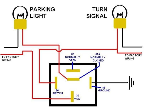
Before diving into the wiring diagram, it’s important to know the basic components of a starter relay. The relay consists of four terminals – battery, ignition switch, starter motor, and ground. Each terminal serves a specific function in the starting process, and the wiring diagram illustrates how they are connected to ensure proper operation.
 5 Pin Starter Relay Wiring Diagram (stewart-switch.com)
One common wiring diagram for a starter relay includes connecting the battery terminal to the positive terminal of the battery, the ignition switch terminal to the ignition switch, the starter motor terminal to the starter motor, and the ground terminal to the vehicle’s chassis. This simple diagram shows the flow of electricity from the battery to the starter motor when the ignition switch is turned.
It’s important to follow the wiring diagram carefully when installing a starter relay to prevent any electrical issues or damage to the vehicle. Checking the connections and ensuring that the terminals are securely attached can help prevent starting problems down the road. If you’re unsure about the wiring diagram or installation process, it’s always best to consult a professional mechanic for assistance.
In conclusion, understanding the wiring diagram for a starter relay is essential for proper installation and troubleshooting. By following the diagram and ensuring that all connections are secure, you can ensure that your vehicle starts smoothly every time. If you’re ever in doubt, don’t hesitate to seek help from a qualified professional to avoid any potential electrical problems.
