When it comes to installing a tachometer in your vehicle, having a proper wiring diagram is essential. A tachometer, or “tach,” is a device used to measure the RPM (revolutions per minute) of an engine’s crankshaft. It provides valuable information to the driver, allowing them to monitor the engine’s performance and make necessary adjustments.
Without a clear understanding of the wiring diagram, installing a tachometer can be a daunting task. It is important to follow the correct wiring instructions to ensure proper functionality and avoid damaging the vehicle’s electrical system. A tach wiring diagram provides a visual guide on how to connect the tachometer to the vehicle’s ignition system and other necessary components.
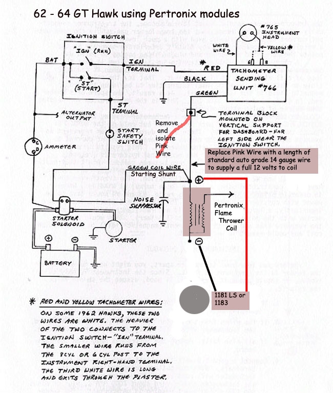
 Pertronix Wiring Diagram With Factory Tach (diagramweb.net)
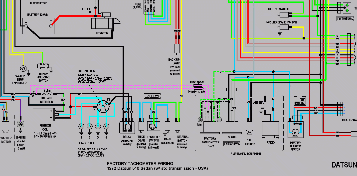
Tach Wiring Diagram
Typically, a tach wiring diagram will include color-coded wires that indicate where each wire should be connected. It will also specify which wires need to be connected to the ignition switch, ground, and the tachometer signal wire. Following the diagram carefully will ensure that the tachometer works correctly and provides accurate RPM readings.
One common mistake when installing a tachometer is connecting it to the wrong wires, which can result in inaccurate readings or even damage to the tachometer. By referring to a tach wiring diagram, you can avoid these pitfalls and ensure a successful installation.
In addition to the wiring diagram, it is important to use the proper tools and equipment when installing a tachometer. This may include wire strippers, electrical tape, and a multimeter to test connections. It is also recommended to consult a professional or refer to the vehicle’s service manual if you are unsure about any step in the installation process.
Overall, a tach wiring diagram is an invaluable resource when installing a tachometer in your vehicle. By following the diagram carefully and using the appropriate tools, you can successfully add this useful device to your vehicle and monitor your engine’s performance with ease.
So, if you are planning to install a tachometer in your vehicle, make sure to refer to a tach wiring diagram to ensure a smooth and trouble-free installation process.
