When it comes to networking, having the correct wiring diagram for an RJ45 connector is essential. RJ45 connectors are commonly used for Ethernet connections and having the right wiring can ensure a stable and reliable network connection. Understanding how to wire an RJ45 connector can save you time and frustration when setting up your network.
Whether you are setting up a home network or working in a professional IT environment, knowing how to wire an RJ45 connector is a valuable skill. With the right wiring diagram, you can easily connect your devices and ensure that data is transmitted efficiently and securely.
 Wiring Diagram Clipart Clipground (clipground.com)
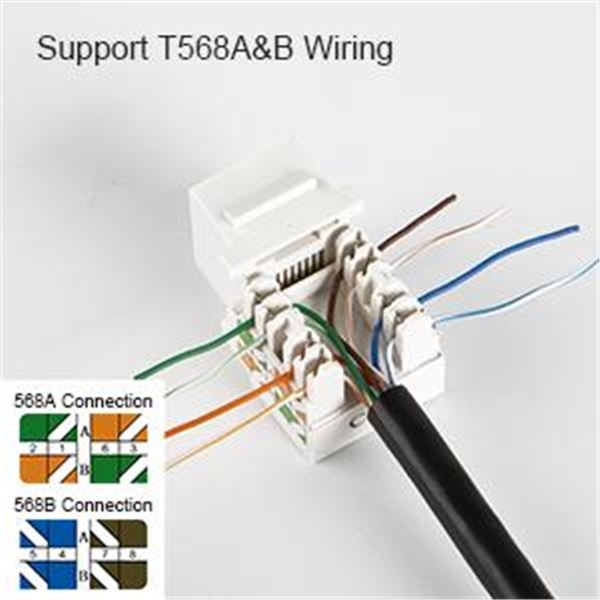
There are two common wiring standards for RJ45 connectors: T568A and T568B. The wiring diagram for each standard specifies the order in which the individual wires should be connected to the connector. By following the correct wiring diagram, you can ensure that your network connection is set up correctly.
For T568A wiring, the order of the wires from left to right is white-green, green, white-orange, blue, white-blue, orange, white-brown, and brown. For T568B wiring, the order is white-orange, orange, white-green, blue, white-blue, green, white-brown, and brown. It is important to follow one of these standards consistently when wiring RJ45 connectors to avoid connectivity issues.
When wiring an RJ45 connector, it is important to use a crimping tool to secure the wires in place. The wires should be stripped to the appropriate length and arranged according to the wiring diagram before crimping the connector onto the cable. Once the connector is crimped, you can test the connection using a network cable tester to ensure that the wiring is correct.
In conclusion, having the correct wiring diagram for an RJ45 connector is crucial for setting up a reliable network connection. By following the T568A or T568B wiring standards and using the right tools, you can ensure that your network is set up correctly and functions efficiently. With the right knowledge and preparation, you can easily wire RJ45 connectors and create a stable network for your devices.