When it comes to wiring a 3 way switch, it can be a bit confusing for those who are not familiar with electrical work. One common scenario is having the power source located at the switch. In this case, the wiring diagram may look a bit different compared to when the power source is at the light fixture.
Having the power at the switch means that the power source is coming into one of the switches instead of the light fixture. This setup can be useful in certain situations, especially when you want to control a single light from multiple locations.
 3 Way Switch Wiring Diagram Pdf Wiring A Honeywell 3 Way Timer Switch (vectorjanel.blogspot.com)
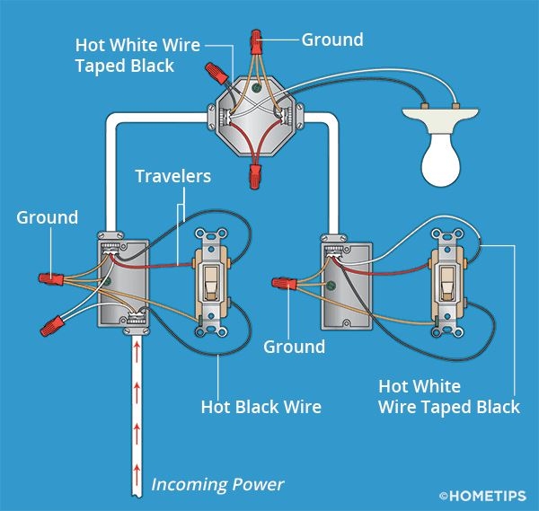
Here is a simple wiring diagram for a 3 way switch with the power at the switch:
1. Start by turning off the power to the circuit at the breaker box to ensure safety during the installation process.
2. Connect the power source (black wire) to the common terminal of the first switch. The common terminal is usually labeled as “COM” on the switch.
3. Connect the traveler wires (usually red and black) to the traveler terminals on the first switch. These terminals are typically labeled as “T1” and “T2.”
4. Run a 3-wire cable from the first switch to the second switch, connecting the traveler wires from the first switch to the traveler terminals on the second switch.
5. Finally, connect the light fixture to the common terminal on the second switch. The light fixture should be connected to the switch with the power source.
With this setup, you can control the light fixture from either switch, allowing for more flexibility in how you use the lighting in your space.
In conclusion, wiring a 3 way switch with the power at the switch can be a useful configuration for certain situations. By following the proper wiring diagram and ensuring safety measures are in place, you can successfully install a 3 way switch with the power at the switch in your home.