3 way switches are commonly used in homes to control a light fixture from two different locations. This type of switch allows for more flexibility in controlling the lighting in a room. Understanding how to wire a 3 way switch is essential for any homeowner or electrician.
When wiring a 3 way switch, it’s important to follow the correct diagram to ensure that the switch functions properly. The wiring diagram will show you the connections between the switches, the power source, and the light fixture. Each wire must be connected to the correct terminal for the switch to work correctly.
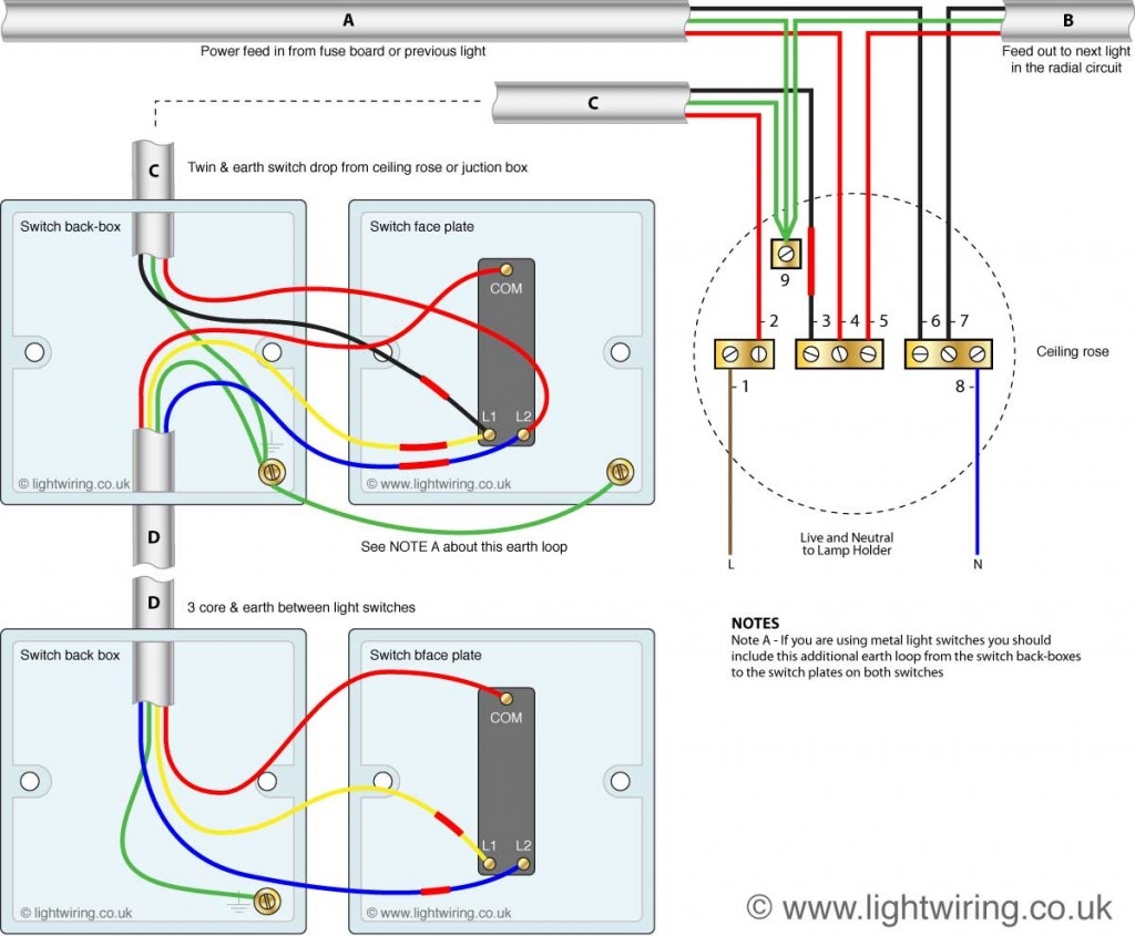
 DIAGRAM 3 Way Switch Wiring Diagram Images WIRINGSCHEMA COM (wiringschema.com)
Typically, a 3 way switch wiring diagram will show three terminals on each switch. These terminals are labeled as “common,” “traveler,” and “ground.” The common terminal is where the power source is connected, while the traveler terminals are used to connect the switches together. The ground terminal is for the grounding wire.
To wire a 3 way switch, you will need to connect the power source to the common terminal on one switch, and then connect the traveler wires to the other terminals on each switch. The traveler wires will run between the switches, allowing them to communicate with each other and control the light fixture.
It’s important to note that when wiring a 3 way switch, the traveler wires must be connected to the correct terminals on each switch. If the wires are not connected properly, the switches will not function correctly and the light fixture may not turn on. Following a wiring diagram is crucial to ensure that the switches are wired correctly.
Overall, understanding how to wire a 3 way switch is essential for anyone looking to install or repair lighting in their home. By following the correct wiring diagram and connecting the wires to the proper terminals, you can ensure that your switches function correctly and control the lighting in your room effectively.