When it comes to upgrading or replacing the alternator in your vehicle, understanding the wiring diagram is crucial. The 3 wire alternator wiring diagram is a common setup in many vehicles, providing a reliable power source for the battery and electrical system.
With a clear understanding of how the 3 wire alternator wiring diagram works, you can ensure a smooth installation process and proper functioning of your vehicle’s electrical system.
 Bosch 3 Wire Alternator Wiring Diagram (axiom-northwest.com)
Understanding the Wiring Diagram
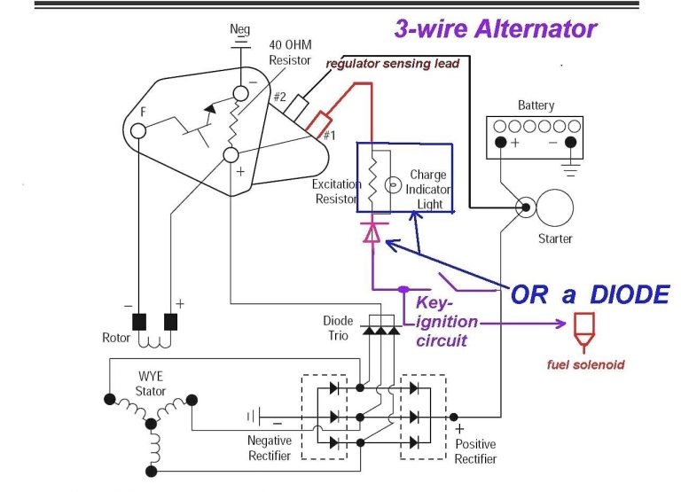
The 3 wire alternator wiring diagram typically consists of three main wires: the battery wire, the field wire, and the stator wire. The battery wire is responsible for supplying power from the alternator to the battery, ensuring a constant charge. The field wire controls the voltage regulator, while the stator wire generates the electrical current needed to power the vehicle’s electrical system.
It is important to follow the wiring diagram carefully to ensure that each wire is connected to the correct terminal on the alternator. This will help prevent any electrical issues and ensure that the alternator functions properly.
When installing a new alternator or replacing the existing one, be sure to check the wiring diagram to ensure that all connections are made correctly. This will help prevent any potential damage to the alternator or electrical system of the vehicle.
Overall, understanding the 3 wire alternator wiring diagram is essential for maintaining the proper functioning of your vehicle’s electrical system. By following the diagram and making the correct connections, you can ensure a reliable power source for your battery and electrical components.
Whether you are a DIY enthusiast or a professional mechanic, having a good grasp of the 3 wire alternator wiring diagram will help you tackle any alternator-related issues with confidence and ease.