When it comes to installing a 4 wire oxygen sensor in your vehicle, it’s important to understand the wiring diagram to ensure proper functioning. The oxygen sensor plays a crucial role in monitoring the exhaust gases and helping the engine adjust the air-fuel mixture for optimal performance.
Before diving into the wiring diagram, it’s essential to know the purpose of each wire in the sensor. The four wires typically include two for the sensor’s heater element and two for the signal output. Understanding this will make the wiring process much simpler.
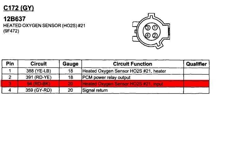
 4 Wire Oxygen Sensor Wiring Diagram Cadician 39 S Blog (2020cadillac.com)
One of the wires is for the sensor’s ground, while another is for the power supply to the heater element. The remaining two wires are for the signal output, one being the signal wire and the other the reference wire. These wires are crucial for the sensor to send accurate readings to the engine control unit.
When connecting the sensor, ensure that the ground wire is properly grounded to the vehicle’s chassis. The power supply wire should receive voltage from the engine control unit to power the heater element. The signal and reference wires must be connected to the appropriate terminals to ensure accurate readings.
It’s important to refer to the vehicle’s wiring diagram or consult a professional if you’re unsure about connecting the sensor. Incorrect wiring can lead to faulty readings and potentially damage the sensor or the engine. Proper installation is crucial for the sensor to function correctly and help the engine run efficiently.
In conclusion, understanding the 4 wire oxygen sensor wiring diagram is essential for proper installation and functioning. Taking the time to familiarize yourself with the wires and their purposes will ensure a successful installation process. Remember to double-check the connections and consult a professional if needed to avoid any issues down the road.