When it comes to wiring a 5 pin relay, it’s important to understand how the relay works and how to properly connect it to your electrical system. A relay is a switch that uses a small current to control a larger current, allowing you to control high-power devices with a low-power signal. Understanding the wiring diagram is crucial to ensure that your relay functions correctly and safely.
Before diving into the wiring diagram, it’s important to identify the pins on your relay. A 5 pin relay will typically have two pins for the coil, which is the part of the relay that receives the control signal. The other three pins are for the normally open (NO), normally closed (NC), and common connections. These pins allow you to control the flow of current through the relay.
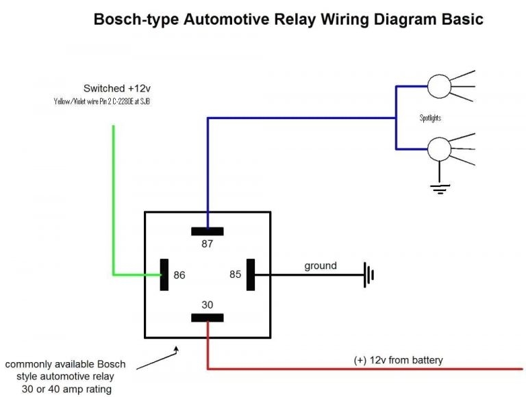
 Four Pin Relay Wiring Diagram (stewart-switch.com)
Now, let’s take a look at the wiring diagram for a 5 pin relay. The coil pins are typically labeled as A and B, with A being the positive connection and B being the negative connection. The NO pin is where the high-power device is connected when the relay is activated, while the NC pin is where the device is connected when the relay is deactivated. The common pin is used to connect the power source to the relay.
When wiring the relay, it’s important to connect the coil pins to a power source with the correct polarity. The NO pin should be connected to the device you want to control, while the NC pin can be left disconnected if not in use. The common pin should be connected to the power source, completing the circuit. It’s also important to use the appropriate gauge wire for the current being controlled by the relay to prevent overheating and potential damage.
In conclusion, understanding the wiring diagram for a 5 pin relay is essential for proper installation and operation. By following the correct wiring connections and using the appropriate wire gauge, you can ensure that your relay functions safely and reliably. Whether you’re controlling lights, motors, or other high-power devices, a 5 pin relay is a versatile component that can help automate your electrical system.