When it comes to installing a thermostat in your home, it’s important to have the right wiring diagram to ensure everything is connected properly. One popular brand of thermostat is Honeywell, known for its reliability and ease of use. In this article, we will discuss the 7 wire Honeywell thermostat wiring diagram to help you with your installation process.
Having a clear understanding of how to wire your thermostat is crucial to ensure that your heating and cooling system functions correctly. The 7 wire Honeywell thermostat wiring diagram will provide you with a step-by-step guide on how to connect each wire properly to the thermostat and HVAC system.
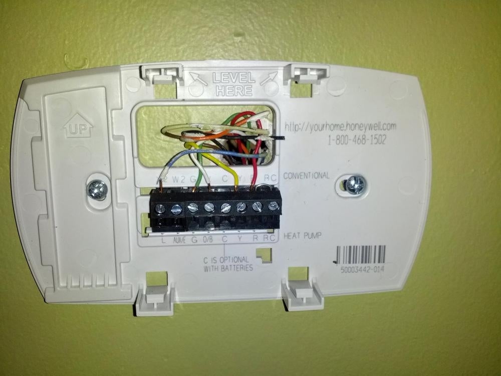
 Honeywell Heat Pump Thermostat Wiring Diagram Sample Wiring Diagram (faceitsalon.com)
Typically, the 7 wire Honeywell thermostat wiring diagram will include labels for each wire, such as R, C, W, Y, G, O, and B. These labels correspond to specific functions, such as power (R), common (C), heating (W), cooling (Y), fan (G), reversing valve for heat pump (O), and second stage cooling (B). By following the diagram, you can easily identify where each wire should be connected.
It’s important to note that the wiring diagram may vary depending on the model of your Honeywell thermostat and HVAC system. Before proceeding with the installation, make sure to carefully read the instructions provided by Honeywell and consult with a professional if needed. This will help to ensure that your thermostat is installed correctly and functions properly.
In conclusion, understanding the 7 wire Honeywell thermostat wiring diagram is essential for a successful installation. By following the diagram and guidelines provided by Honeywell, you can easily connect each wire to the appropriate terminals and set up your thermostat with confidence. If you encounter any difficulties during the installation process, don’t hesitate to seek help from a professional to avoid any potential issues down the line.