When it comes to wiring an ignition switch, having the correct diagram is essential. A 5 pole ignition switch wiring diagram is a helpful tool for anyone looking to install or repair their ignition system. By following the diagram, you can ensure that your ignition switch is wired correctly and functions properly.
Whether you are a novice or experienced with electrical wiring, having a diagram to reference can make the process much easier. It eliminates the guesswork and ensures that you are connecting the wires in the correct order. This can prevent costly mistakes and potential damage to your vehicle.
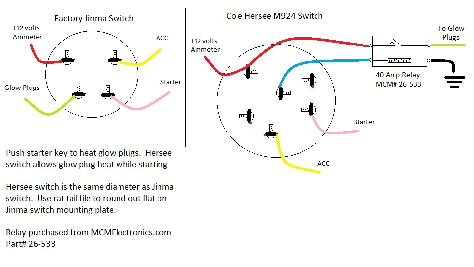
 5 Pole Ignition Switch Wiring Diagram (www.yardguides.com)
When looking at a 5 pole ignition switch wiring diagram, you will typically see five terminals labeled with letters or numbers. These terminals correspond to the different wires that need to be connected to the switch. By following the diagram, you can easily identify which wire goes to each terminal and make the appropriate connections.
One common mistake that people make when wiring an ignition switch is mixing up the wires or connecting them to the wrong terminals. This can result in the ignition system not working properly or even causing damage to other components. By using a diagram, you can avoid these issues and ensure that your ignition switch is wired correctly.
Overall, having a 5 pole ignition switch wiring diagram can be a valuable resource for anyone working on their ignition system. It provides a clear and concise guide for connecting the wires to the switch and ensures that everything is done correctly. By following the diagram, you can have peace of mind knowing that your ignition system is functioning properly.
So, whether you are installing a new ignition switch or troubleshooting an existing one, be sure to consult a wiring diagram to make the process easier and more efficient. With the right tools and information, you can successfully wire your ignition switch and keep your vehicle running smoothly.