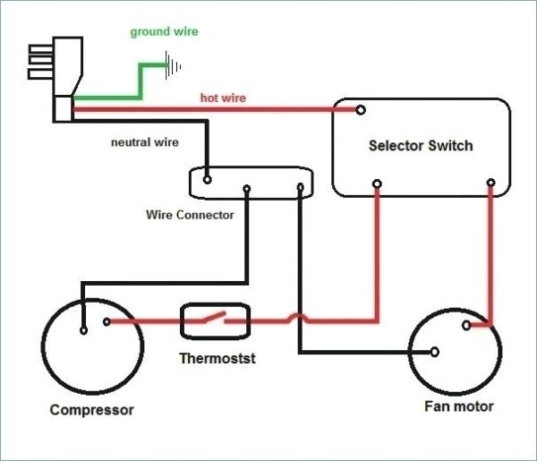
When it comes to air conditioning systems, proper wiring is crucial for optimal performance and safety. The wiring diagram of an air conditioning system shows the electrical connections between various components, such as the compressor, condenser, fan motor, and thermostat. Understanding this diagram is essential for technicians when installing or troubleshooting an AC unit.
Each component in an air conditioning system has a specific function and must be connected correctly to ensure efficient operation. The wiring diagram provides a visual representation of how these components are interconnected, allowing technicians to identify and fix any wiring issues that may arise.
 Basic Air Conditioning Wiring Diagram (impotents8frwire.z21.web.core.windows.ne…)
Typically, the wiring diagram of an air conditioning system includes color-coded wires, labels, and symbols to indicate the different electrical connections. It also shows the power supply source, ground connections, and control circuits that regulate the system’s operation.
One common type of wiring diagram for air conditioning systems is the ladder diagram, which uses horizontal lines to represent wires and vertical lines to show the connections between components. This diagram is easy to follow and helps technicians troubleshoot electrical problems quickly.
Properly understanding and interpreting the wiring diagram of an air conditioning system is essential for ensuring the system operates safely and efficiently. Incorrect wiring can lead to malfunctions, breakdowns, or even electrical hazards, so it’s crucial to follow the diagram carefully during installation or repair work.
In conclusion, the wiring diagram of an air conditioning system is a vital tool for technicians working on AC units. By following this diagram accurately, technicians can ensure that all electrical connections are correct, leading to a properly functioning and safe air conditioning system.
