When it comes to electrical systems in vehicles or other machinery, relays play a crucial role in controlling various components. A 5 pin relay is commonly used in automotive applications to control accessories such as lights, fans, or motors. Understanding how to wire a 5 pin relay is essential for proper installation and operation.
Relays are electromechanical switches that use a small amount of current to control a larger current. A 5 pin relay typically has five pins labeled as follows: 85 (coil power), 86 (coil ground), 87 (normally open), 30 (common), and 87a (normally closed). Each pin serves a specific function in the relay circuit.
 How A 5 Pin Relay Works Youtube 5 Prong Relay Wiring Diagram (2020cadillac.com)
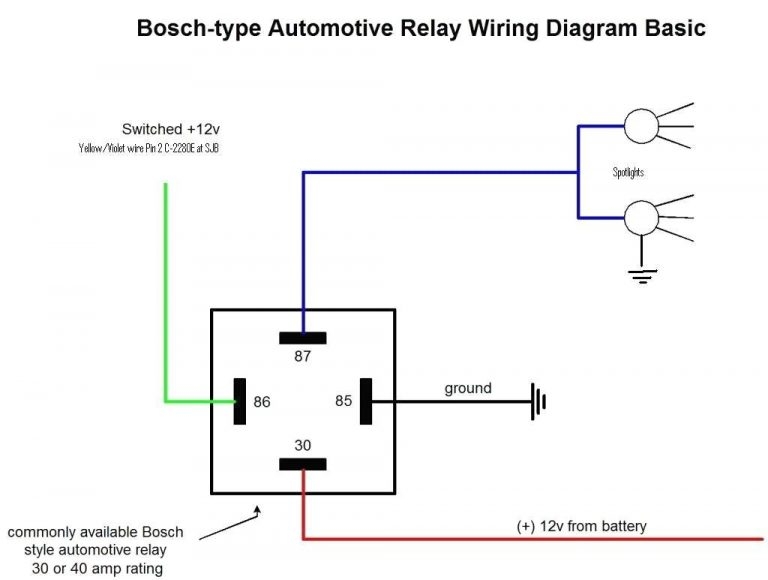
When wiring a 5 pin relay, it is important to pay attention to the pin configuration and ensure proper connection. The power source should be connected to pin 30, which is the common terminal. Pin 87 is the normally open contact, and pin 87a is the normally closed contact. Pins 85 and 86 are used to energize the relay coil.
One common wiring diagram for a 5 pin relay involves connecting the power source to pin 30, the accessory to pin 87, and grounding pin 86. Pin 85 can be connected to a switch that will energize the coil when activated. This configuration allows the relay to control the accessory based on the switch input.
It is important to follow the manufacturer’s instructions and specifications when wiring a 5 pin relay to ensure proper operation and avoid any potential issues. Testing the relay after installation is also recommended to verify that it is functioning correctly. With the right wiring diagram and proper installation, a 5 pin relay can effectively control various components in a vehicle or machinery.
Overall, understanding how to wire a 5 pin relay is essential for anyone working with automotive electrical systems. By following the correct wiring diagram and making sure all connections are secure, you can ensure the reliable operation of your relay-controlled accessories. Proper installation and testing are key to successful relay operation.