Switch 2 Way Wiring Diagram is a common electrical wiring configuration used in many homes and buildings. It allows for a single light fixture to be controlled from two different locations, such as a hallway with switches at both ends. This type of wiring is also known as a “three-way switch” setup.
With a Switch 2 Way Wiring Diagram, it is important to understand the basic principles of how the circuit works. There are two switches involved, usually referred to as Switch A and Switch B. When one switch is in the “on” position, the other switch must be in the opposite position to control the light fixture.
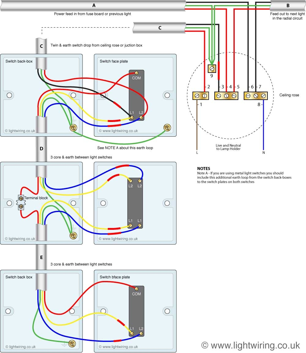
 Light Switch 2 Way Wiring Diagram AndersGarnow (www.andersgarnow.com)
One common mistake when wiring a switch 2 way setup is not properly identifying the “traveler” wires that connect the switches. These wires are typically colored differently than the hot and neutral wires, and must be installed correctly for the circuit to function properly.
It is also important to note that a Switch 2 Way Wiring Diagram requires a special type of switch called a three-way switch. These switches have three terminals instead of the usual two, allowing for the multiple wiring configurations needed for this setup.
When installing a Switch 2 Way Wiring Diagram, it is recommended to consult a professional electrician to ensure the job is done safely and correctly. Working with electricity can be dangerous, and mistakes in wiring can lead to electrical shocks or fires.
In conclusion, Switch 2 Way Wiring Diagram is a useful and common wiring configuration that allows for convenient control of a single light fixture from two different locations. By understanding the basics of how the circuit works and following proper installation procedures, this type of wiring can be safely implemented in your home or building.