Contactor wiring diagrams are essential for understanding how to properly connect electrical components in a circuit. A contactor is an electrical relay that controls the flow of electricity to a load. It is commonly used in HVAC systems, lighting controls, and industrial machinery.
Understanding how to wire a contactor is crucial for ensuring the safe and efficient operation of electrical systems. By following a wiring diagram, you can easily connect the contactor to other components such as motor starters, switches, and overload relays.
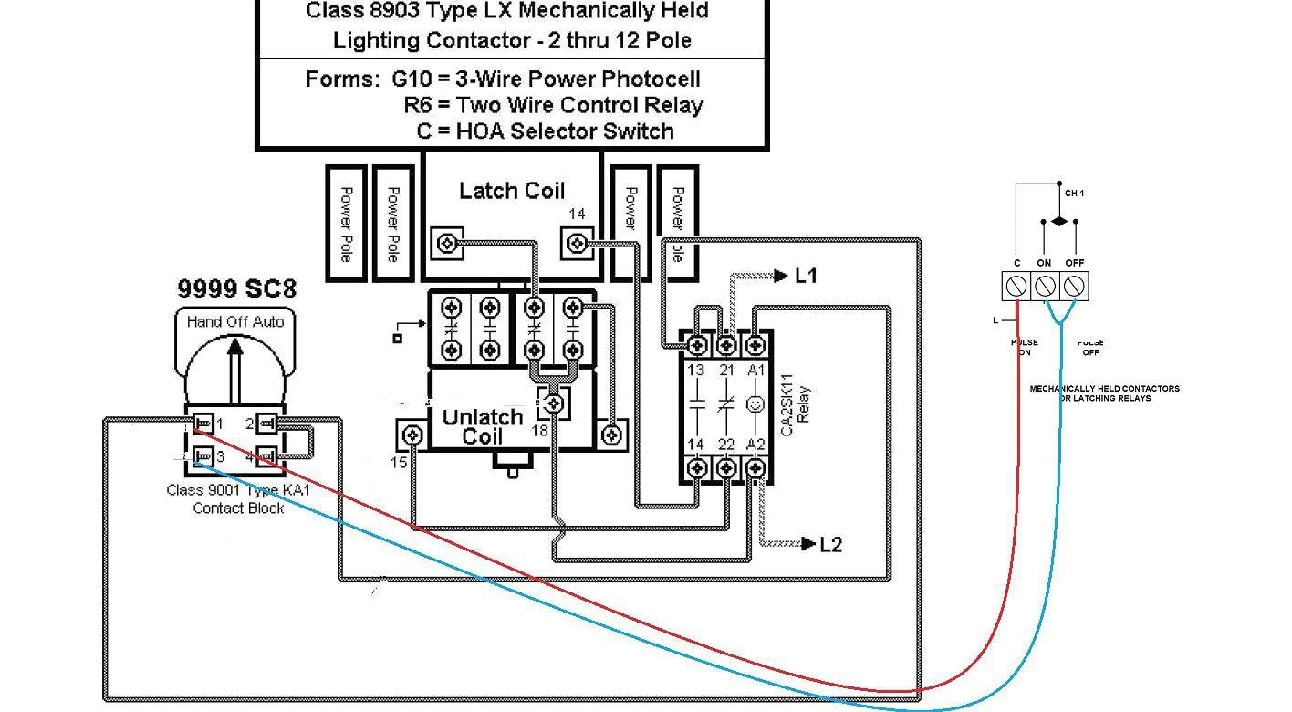
 240 Volt Contactor Wiring Diagram Wiring Diagram (annawiringdiagram.com)
When wiring a contactor, it is important to follow the manufacturer’s instructions and adhere to local electrical codes. Improper wiring can lead to equipment damage, electrical hazards, and even fire risks. Therefore, always consult a qualified electrician if you are unsure about the wiring process.
To begin wiring a contactor, first identify the main power supply and the load that the contactor will control. Next, connect the line and load wires to the appropriate terminals on the contactor. Make sure to secure the connections using terminal screws or crimp connectors.
Once the wiring is complete, test the contactor by energizing the control circuit. Verify that the contactor engages and disengages properly when the control signal is applied. If the contactor fails to operate correctly, double-check the wiring connections and troubleshoot any potential issues.
In conclusion, understanding how to wire a contactor is essential for maintaining the safety and efficiency of electrical systems. By following a wiring diagram and adhering to best practices, you can ensure that the contactor operates reliably and safely. Remember to always consult a professional electrician if you are unsure about any aspect of the wiring process.