When it comes to electrical safety in your home, GFCI outlets are a must-have. These outlets are designed to protect you from electrical shocks by quickly shutting off power when they detect a ground fault. Understanding how to wire a GFCI outlet is essential for ensuring that it functions properly and keeps you safe.
Before you begin wiring a GFCI outlet, it’s important to turn off the power to the circuit you’ll be working on. This can be done by flipping the breaker in your electrical panel. Once the power is off, you can proceed with installing the GFCI outlet.
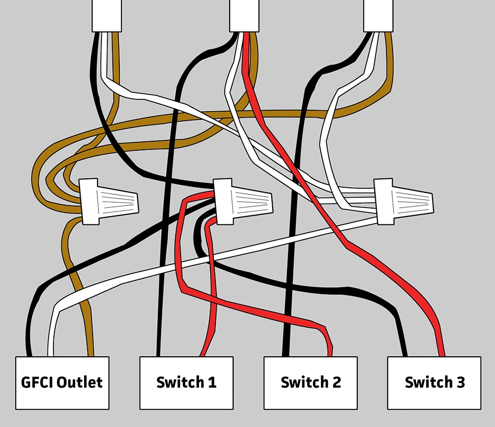
 Gfci Outlet Wiring Diagram Database (www.got2bwireless.com)
Start by removing the old outlet from the electrical box and disconnecting the wires. You’ll notice that a GFCI outlet has more screw terminals than a standard outlet. The terminals are labeled “Line” and “Load.” The “Line” terminals are where the power source wires will connect, while the “Load” terminals are for additional outlets down the line.
Next, you’ll need to connect the black (hot) wire to the brass terminal, the white (neutral) wire to the silver terminal, and the green or bare copper wire to the green screw for grounding. Make sure to tighten the screws securely to ensure a good connection.
After all the wires are connected, carefully fold them back into the electrical box and secure the GFCI outlet in place. Finally, turn the power back on at the breaker and test the outlet to make sure it’s working properly. You can do this by pressing the “Test” button on the outlet, which should trip the GFCI and cut off power.
Overall, understanding how to wire a GFCI outlet is crucial for maintaining a safe electrical system in your home. By following the proper wiring diagram and installation steps, you can ensure that your GFCI outlet functions correctly and provides the protection you need against electrical hazards.