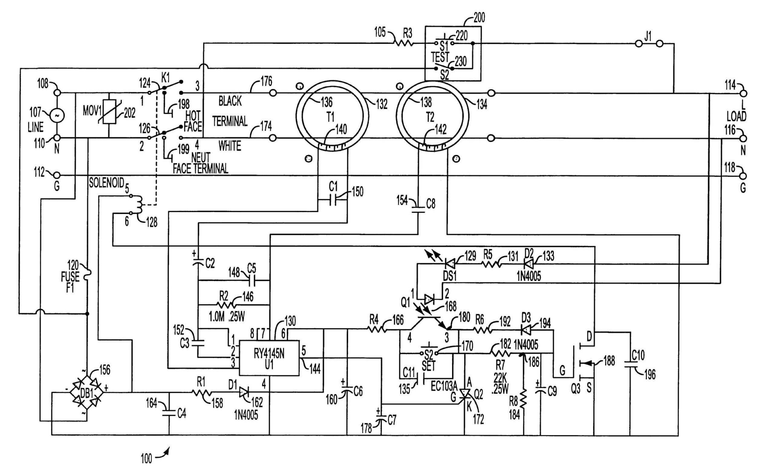
 DIAGRAM Wiring Diagram Gfci Circuit MYDIAGRAM ONLINE (mydiagram.online)
Understanding GFCI Wiring Diagram
Ground Fault Circuit Interrupter (GFCI) outlets are an essential safety feature in modern homes. These outlets are designed to protect you from electrical shocks by quickly shutting off power when a ground fault is detected. Understanding the wiring diagram of a GFCI outlet is crucial for proper installation and maintenance.
GFCI outlets have different wiring requirements compared to regular outlets. They have Line and Load terminals, as well as a Ground terminal. The Line terminals are where the power source is connected, while the Load terminals are where additional outlets are connected for protection. It is important to follow the wiring diagram carefully to ensure the GFCI outlet functions properly.
GFCI Wiring Diagram
When wiring a GFCI outlet, the Line terminals should be connected to the hot and neutral wires from the power source. The Load terminals should then be connected to the hot and neutral wires going to the additional outlets. The Ground terminal should be connected to the grounding wire for added safety.
It is important to test the GFCI outlet after installation to ensure it is working correctly. Press the Test button on the outlet to simulate a ground fault and see if the power shuts off. If the outlet does not trip, there may be a wiring issue that needs to be addressed.
Properly installing and maintaining GFCI outlets in your home can help prevent electrical accidents and protect your family from harm. By understanding the wiring diagram and following the correct installation procedures, you can ensure the safety of your electrical system.
In conclusion, GFCI outlets are an important safety feature in modern homes and require proper wiring for effective operation. By following the wiring diagram and testing the outlet after installation, you can ensure that your electrical system is safe and secure. Always consult a professional electrician if you are unsure about wiring GFCI outlets in your home.
Download and Print Gfci Wiring Diagram Listed below
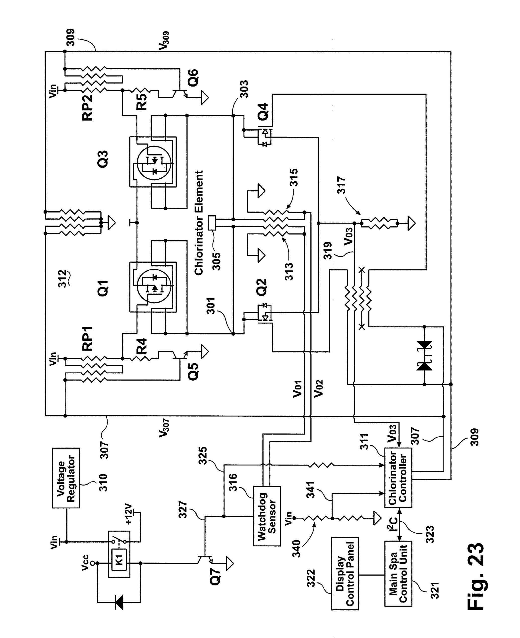 2 Pole Gfci Breaker Wiring Diagram Wiring Diagram (annawiringdiagram.com)
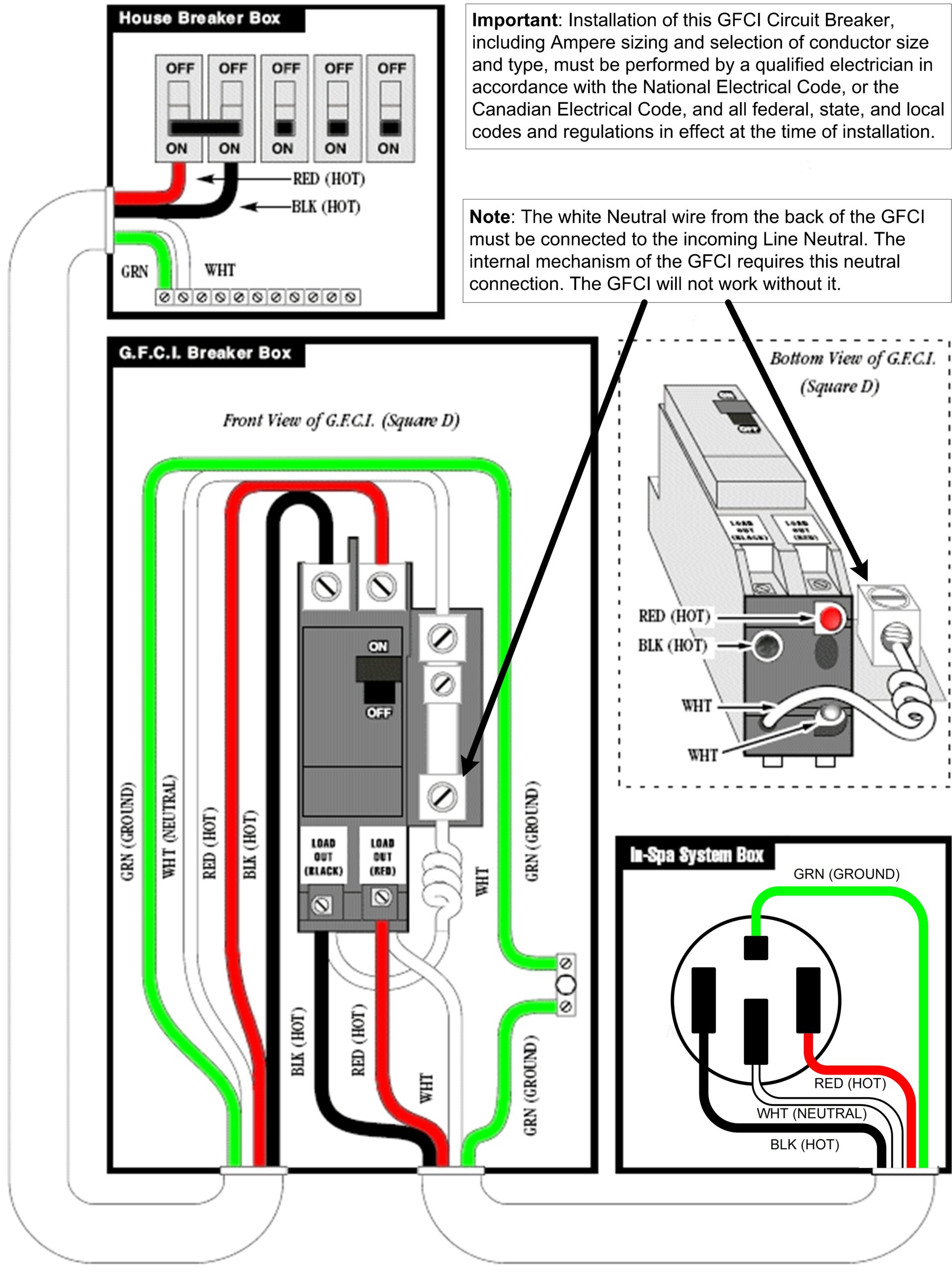 2 Pole Gfci Breaker Wiring Diagram Wiring Diagram (annawiringdiagram.com)
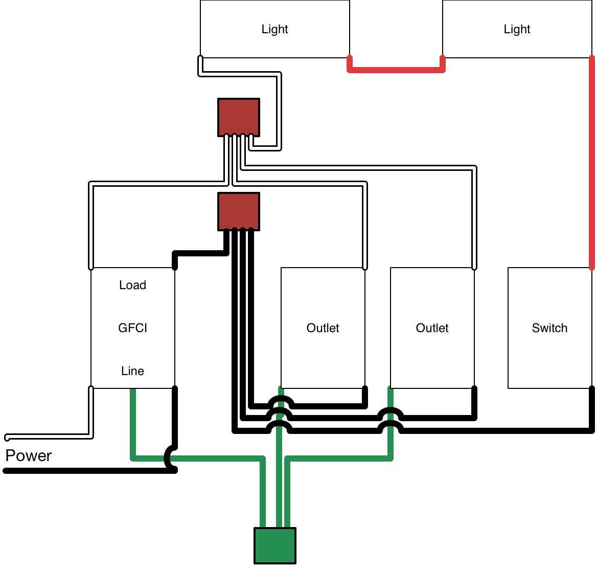 2Wire Gfci Wiring Diagram Wiring Diagrams Thumbs Gfci Wiring (2020cadillac.com)
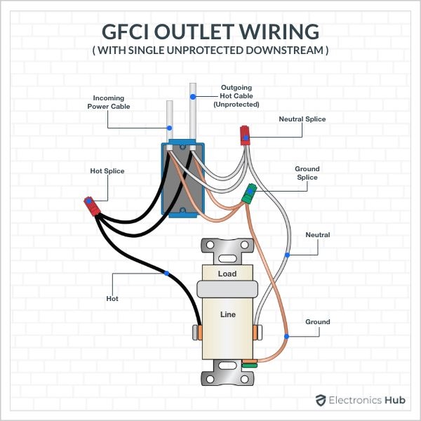 Gfci Outlet Wiring Diagram (stewart-switch.com)
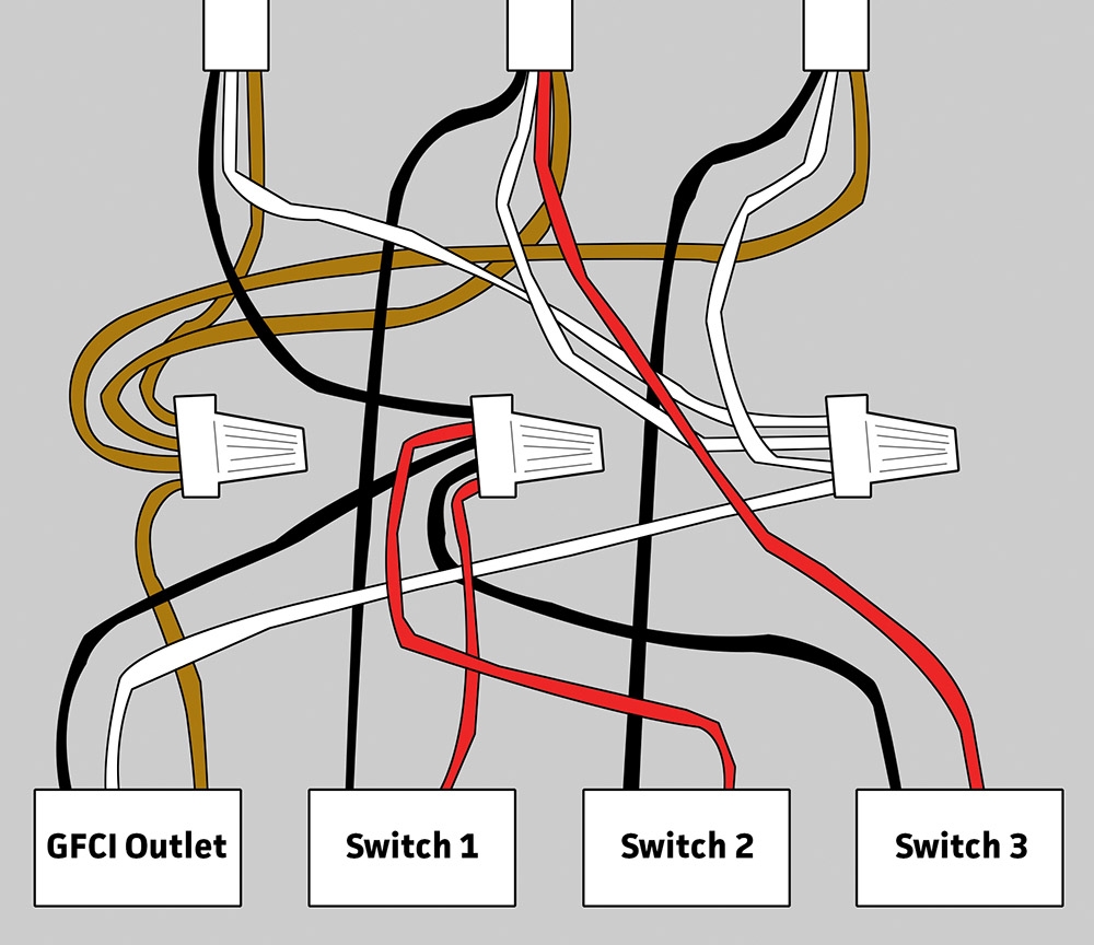 Gfci Outlet Wiring Diagram Wiring Diagram (annawiringdiagram.com)
Gfci Wiring Diagram
To sum up, grasping and utilizing Gfci Wiring Diagram is an vital skill for anyone involved in electrical work, from novices to veteran technicians. These diagrams serve as blueprints that show the connections and functions of electrical circuits, making troubleshooting, installation, and maintenance far more manageable.
If you’re working on a small home lighting system or a large-scale industrial setup, a well-drawn Gfci Wiring Diagram can save time, reduce mistakes, and ensure safety.
For beginners Gfci Wiring Diagram, begin with simple projects, explore real-life examples, and don’t hesitate to seek guidance. For skilled workers, staying updated with the latest standards helps you stay relevant.
All in all, Gfci Wiring Diagram are more than just schematic drawings; they are the language of electricity. By mastering and create them, you empower yourself to work more effectively, more safely, and more accurately in any electrical project.
We appreciate your time, and we hope this article Gfci Wiring Diagram has shed light on the power of wiring diagrams.