Ignition coils are an essential component in a vehicle’s ignition system. They are responsible for converting the low voltage from the battery into the high voltage needed to ignite the fuel and air mixture in the engine. Understanding the wiring diagram of an ignition coil is important for proper installation and troubleshooting.
Most ignition coils have three terminals: positive, negative, and a trigger terminal. The positive terminal is connected to the ignition switch, the negative terminal is grounded, and the trigger terminal receives a signal from the engine control module to fire the spark plug.
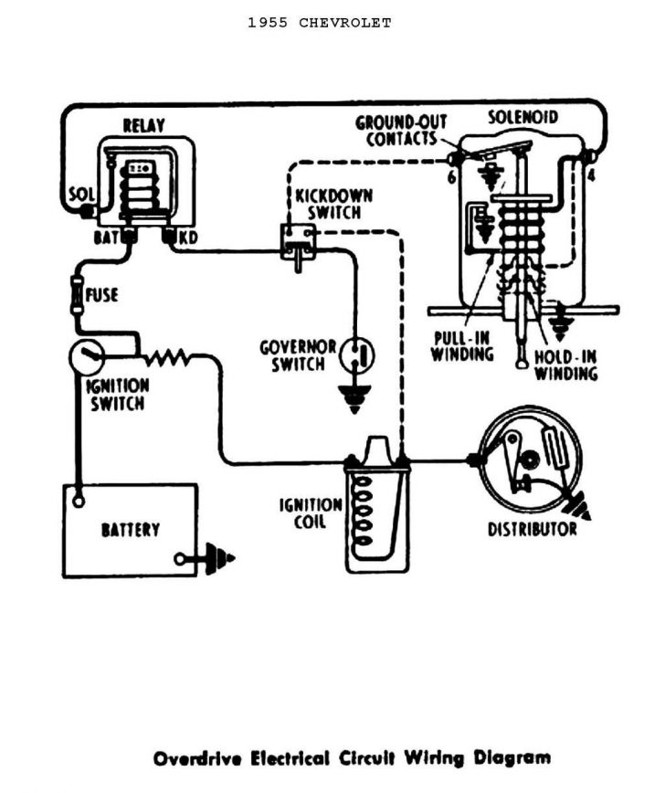
 Pertronix Positive Ground Wiring At How To Wire An Ignition Coil Coil (annawiringdiagram.com)
When wiring an ignition coil, it is crucial to follow the manufacturer’s instructions and the specific wiring diagram for your vehicle. Failure to do so can result in improper ignition timing, misfires, and even damage to the ignition system.
Typically, the positive terminal of the ignition coil is connected to the ignition switch through a resistor or ballast resistor to prevent overheating. The negative terminal is grounded to the engine block or chassis. The trigger terminal receives a signal from the engine control module or distributor to fire the spark plug at the correct time.
It is important to check the wiring diagram for your specific vehicle to ensure proper connections and voltages. Incorrect wiring can lead to engine performance issues and even damage to the ignition system. If you are unsure about the wiring, it is recommended to consult a professional mechanic or refer to the vehicle’s service manual.
In conclusion, understanding the wiring diagram of an ignition coil is crucial for proper installation and troubleshooting. Following the manufacturer’s instructions and the specific wiring diagram for your vehicle will ensure that your ignition system functions correctly. If you are unsure about the wiring, seek professional help to avoid potential damage to your vehicle’s engine.