Single phase motors are commonly used in various applications such as fans, pumps, and compressors. One of the most common types of single phase motors is the capacitor start motor. This type of motor uses a capacitor to provide additional starting torque.
When wiring a single phase motor with a capacitor start, it is important to follow the correct wiring diagram to ensure proper operation. The wiring diagram will show the connections between the motor, capacitor, and power supply, allowing for smooth starting and operation of the motor.
 Single Phase Fan Wiring Diagram With Capacitor Wiring Diagram And (diagram.tntuservices.com)
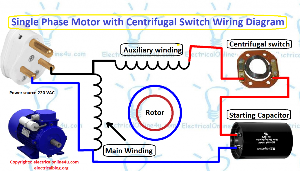
Typically, a single phase motor with capacitor start will have two windings – a main winding and an auxiliary winding. The capacitor is connected in series with the auxiliary winding to create a phase shift, which helps in starting the motor.
In the wiring diagram, the main winding is usually connected directly to the power supply, while the auxiliary winding and capacitor are connected in series. This configuration allows the motor to start with high torque and then run efficiently once it reaches operating speed.
It is important to note that incorrect wiring of a single phase motor with capacitor start can lead to motor failure or inefficient operation. It is recommended to consult the manufacturer’s instructions or a professional electrician when wiring a motor of this type.
Overall, understanding the wiring diagram for a single phase motor with capacitor start is essential for proper installation and operation. By following the correct wiring connections, you can ensure the motor starts smoothly and runs efficiently in your desired application.