 Wiring Diagram For Gfci (axiom-northwest.com)
Wiring A GFCI Outlet Diagram
Wiring a GFCI outlet is an important safety measure that can protect you and your family from electrical shocks. Ground Fault Circuit Interrupter (GFCI) outlets are designed to quickly shut off power in the event of a ground fault, which can occur when electricity flows through an unintended path, such as water or a person.
It is essential to follow a proper wiring diagram when installing a GFCI outlet to ensure it functions correctly and provides the intended protection. Here, we will discuss the steps involved in wiring a GFCI outlet and provide a diagram for reference.
To begin wiring a GFCI outlet, first, turn off the power to the circuit at the breaker box. Remove the old outlet and disconnect the wires. Identify the line (power supply) and load (additional outlets or fixtures) wires. Connect the line wires to the LINE terminals on the GFCI outlet and the load wires to the LOAD terminals. Make sure to follow the specific wiring diagram provided with the outlet.
Once the wires are securely connected, carefully tuck them back into the electrical box and mount the GFCI outlet. Turn the power back on and test the outlet by pressing the “TEST” and “RESET” buttons. The outlet should trip and cut off power when the “TEST” button is pressed, indicating that it is functioning correctly.
It is important to periodically test your GFCI outlet to ensure it is working properly and providing the necessary protection. If you encounter any issues during installation or testing, consult a qualified electrician for assistance.
In conclusion, wiring a GFCI outlet is a straightforward process that can greatly enhance the safety of your electrical system. By following a proper wiring diagram and taking the necessary precautions, you can install a GFCI outlet with confidence and peace of mind.
Download and Print Wiring A Gfci Outlet Diagram Listed below
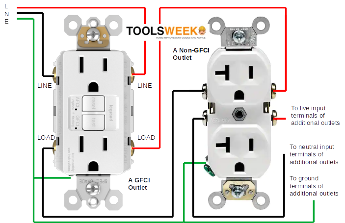 Gfci Outlet Wiring Diagram Outlet Wiring Electrical W Vrogue Co (www.vrogue.co)
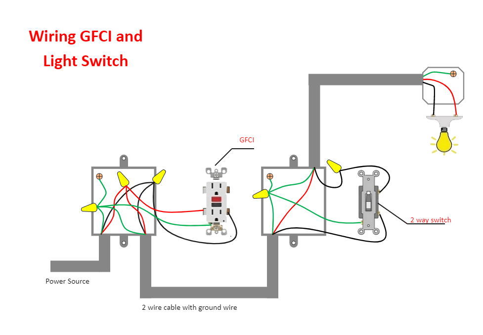 Gfci Outlet Wiring Diagram Outlet Wiring Electrical Wiring 43 OFF (medisur-rgl.com.ar)
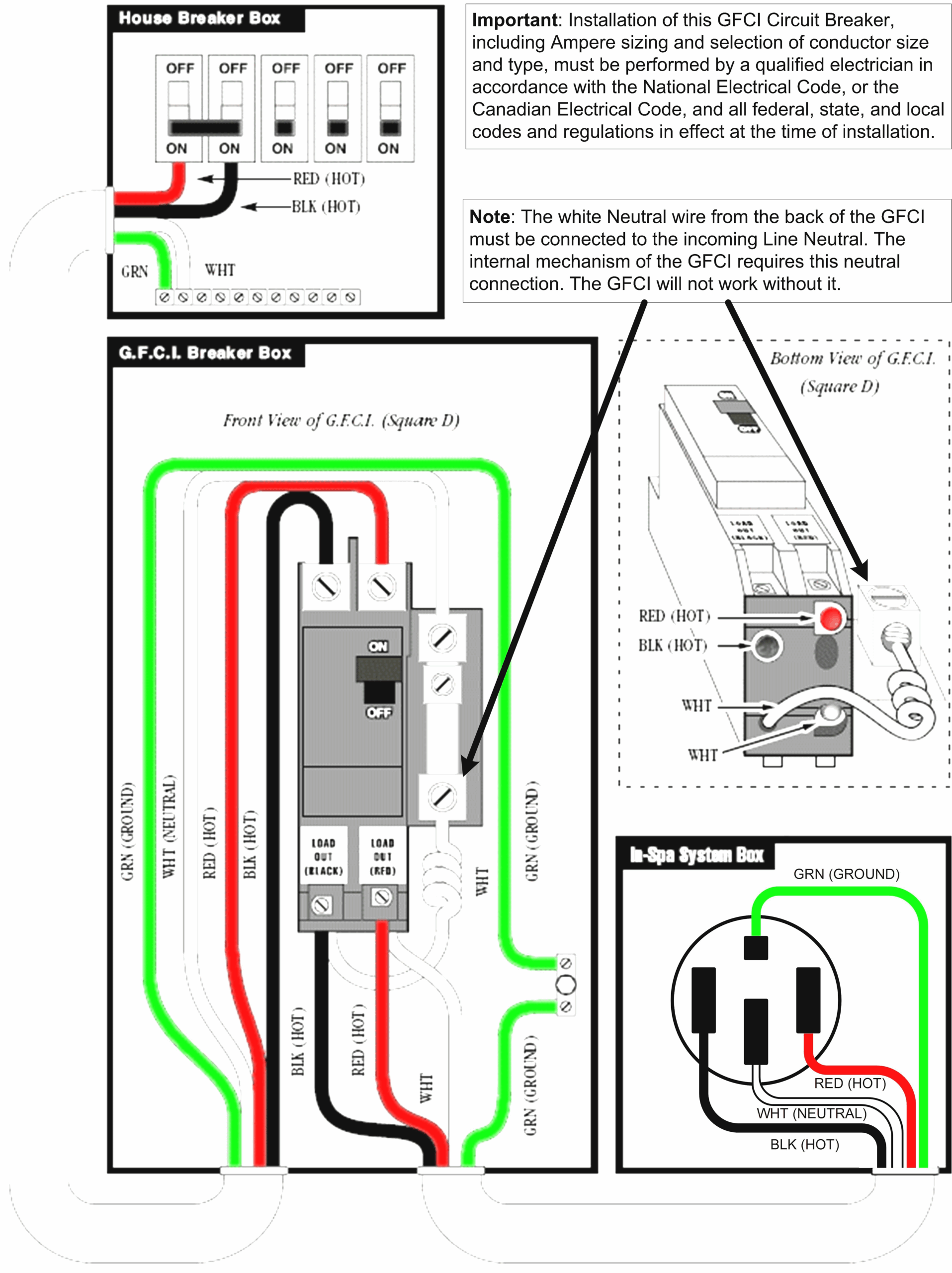 Gfci Multiple Outlet Wiring Diagram Awesome Gfci Outlet Wiring (2020cadillac.com)
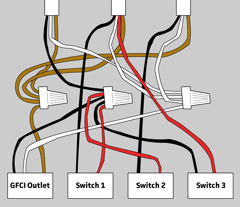 Gfci Outlet Wiring Diagram Wiring Diagram (annawiringdiagram.com)
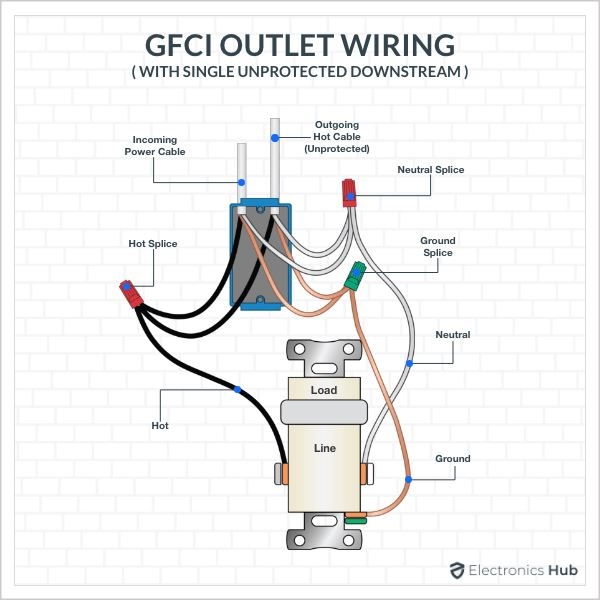 Gfci Outlet Wiring Diagram (stewart-switch.com)
Wiring A Gfci Outlet Diagram
To sum up, grasping and utilizing Wiring A Gfci Outlet Diagram is an important skill for anyone working with electrical systems, from newcomers to experienced electricians. These diagrams function as blueprints that show the connections and functions of electrical circuits, making troubleshooting, setup, and servicing far more efficient.
When you’re working on a basic home lighting system or a complex industrial setup, a well-drawn Wiring A Gfci Outlet Diagram can help avoid delays, reduce mistakes, and improve security.
If you’re new to Wiring A Gfci Outlet Diagram, start small, examine real-life examples, and don’t hesitate to seek guidance. For skilled workers, staying updated with the latest standards helps you stay competitive.
In the end, Wiring A Gfci Outlet Diagram are more than just schematic drawings; they are the blueprint of electricity. By being able to interpret and design them, you equip yourself to work more effectively, safer, and more accurately in any electrical project.
Thank you for reading, and we hope this article Wiring A Gfci Outlet Diagram has given insight into the importance of wiring diagrams.