In the world of networking and telecommunications, the RJ45 connector is an essential component. It is commonly used to connect computers, routers, switches, and other devices to a Local Area Network (LAN) or the internet. Understanding how to wire an RJ45 connector is crucial for ensuring proper connectivity and avoiding network issues.
Whether you are setting up a new network or troubleshooting an existing one, having a clear wiring diagram for RJ45 can make the process much easier. By following the correct wiring scheme, you can ensure that data is transmitted accurately and efficiently between devices.
 Ethernet Coupler Wiring Diagram (wiringdiagramall.blogspot.com)
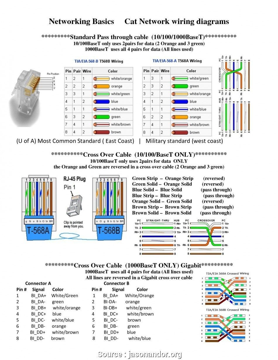
There are two common wiring standards for RJ45 connectors: TIA/EIA 568A and TIA/EIA 568B. Both standards define the pinout or arrangement of wires inside the connector. It is important to use the same standard on both ends of a network cable to maintain consistency and avoid connection problems.
When wiring an RJ45 connector, each of the eight pins must be connected to the corresponding wire in the cable. Pin 1 is typically white-orange, pin 2 is orange, pin 3 is white-green, pin 4 is blue, pin 5 is white-blue, pin 6 is green, pin 7 is white-brown, and pin 8 is brown. Following the correct color coding is essential for proper signal transmission.
To create a wiring diagram for RJ45, you can use a simple chart or table that shows the pin assignments for both 568A and 568B standards. This visual reference can help you quickly identify which wire goes where, making it easier to terminate connectors and troubleshoot connectivity issues.
In conclusion, having a clear wiring diagram for RJ45 is essential for anyone working with networking equipment. By following the correct standards and color coding, you can ensure that your network connections are reliable and efficient. Whether you are a professional network technician or a DIY enthusiast, understanding how to wire an RJ45 connector is a valuable skill that can save you time and frustration.