When it comes to networking, the RJ45 connector is one of the most commonly used connectors for Ethernet cables. It is used to connect devices such as computers, routers, and switches to create a network. Understanding how to wire an RJ45 connector is essential for setting up a reliable network connection.
The RJ45 connector has eight pins that need to be correctly wired to ensure proper connectivity. Each pin serves a specific purpose in transmitting data between devices. By following a wiring diagram, you can easily connect the cables to the RJ45 connector in the correct order.
 Rj45 Connector Wiring Diagram AndersGarnow (www.andersgarnow.com)
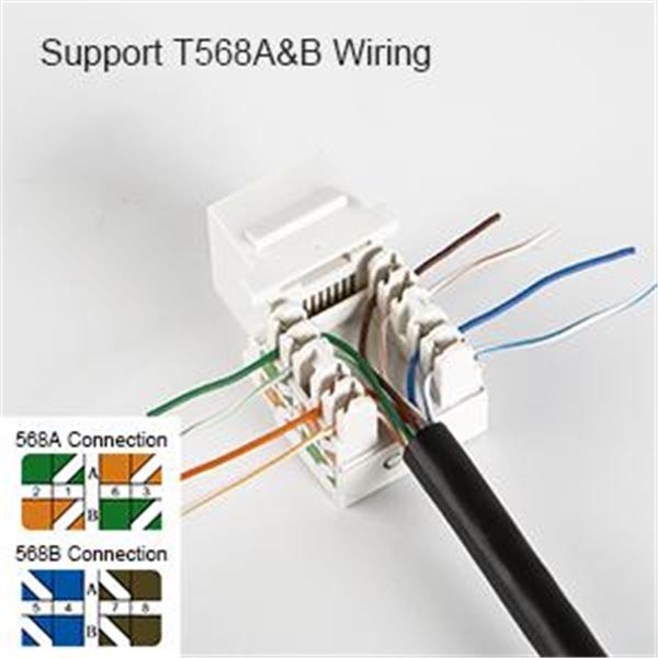
One common wiring diagram for an RJ45 connector is the T-568B standard. This wiring standard specifies the order in which the eight wires should be connected to the pins of the RJ45 connector. The T-568B standard is widely used in Ethernet networking and is considered the most common wiring scheme for RJ45 connectors.
To wire an RJ45 connector using the T-568B standard, the wires are arranged in the following order: white/orange, orange, white/green, blue, white/blue, green, white/brown, brown. By following this wiring diagram and carefully connecting each wire to the corresponding pin of the RJ45 connector, you can ensure a reliable network connection.
It is important to note that there is also another wiring standard called T-568A, which has a slightly different wire arrangement. While both standards are acceptable for Ethernet networking, it is essential to use the same wiring standard on both ends of the cable to avoid connectivity issues.
By understanding the wiring diagram for an RJ45 connector and following the appropriate wiring standard, you can easily set up a network connection that is stable and reliable. Properly wiring the RJ45 connector ensures that data is transmitted accurately between devices, allowing for seamless communication on the network.
In conclusion, knowing how to wire an RJ45 connector is crucial for setting up a network connection. By following a wiring diagram and using the appropriate wiring standard, you can easily connect Ethernet cables to RJ45 connectors and establish a reliable network connection.