When it comes to the ignition system of a vehicle, the ignition coil plays a crucial role. It is responsible for converting the low voltage from the battery into a high voltage needed to ignite the fuel in the engine. Understanding the wiring diagram for the ignition coil is essential for proper installation and troubleshooting.
Having a clear understanding of how the ignition coil is wired can help prevent issues such as misfiring, starting problems, and even engine damage. By following the correct wiring diagram, you can ensure that the ignition coil receives the proper voltage and works efficiently.
 Coil Ignition Wiring Diagram Esquilo Io (esquilo.io)
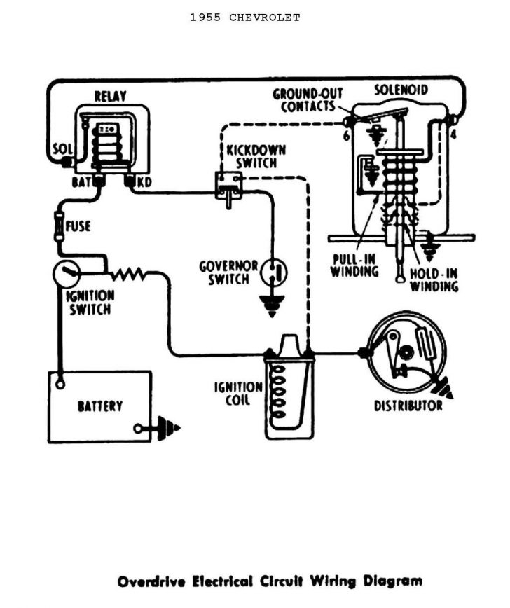
Here is a basic wiring diagram for the ignition coil:
1. The positive terminal of the ignition coil is connected to the ignition switch. This allows the coil to receive power when the key is turned on.
2. The negative terminal of the coil is connected to the points or electronic ignition module. This connection is essential for the coil to discharge the high voltage spark to the spark plugs at the right time.
3. The high voltage output terminal of the coil is connected to the distributor cap, which then distributes the spark to the individual spark plugs in the engine.
4. Some ignition coils also have a secondary winding that is connected to the tachometer. This allows the tachometer to display the engine RPM accurately.
By following this wiring diagram, you can ensure that the ignition coil functions properly and delivers the high voltage spark needed for the engine to run smoothly. Remember to always consult the vehicle’s service manual for the specific wiring diagram for your make and model.